Ручной расчёт установившегося режима кольцевой электрической сети
В данной статье представлен пример ручного расчёта УР кольцевой электрической сети с учётом потерь мощности.
Исходные данные
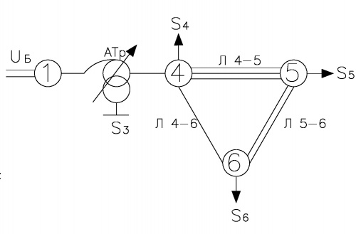
- Исходная схема электрической сети представлена на рисунке 1.
- АТр: АТДЦТН-63000/220/110;
- Параметры линий:
- Марка проводов всех ЛЭП АС-240/32;
- 4-5: 3х60 км;
- 5-6: 2х40 км;
- 4-6: 1х20 км.
- Параметры нагрузок:
- [math]\displaystyle \dot{S}_{3}=4+j\cdot2[/math] МВА;
- [math]\displaystyle \dot{S}_{4}=-10-j\cdot10[/math] МВА;
- [math]\displaystyle \dot{S}_{5}=-40-j\cdot20[/math] МВА;
- [math]\displaystyle \dot{S}_{6}=60+j\cdot30[/math] МВА.
Алгоритм расчёта кольцевой сети
- Расчёт параметров схемы замещения.
- Выбор УПН потоков мощностей.
- Расчёт сети без учета потерь мощности.
- Выбор точки потокораздела.
- Расчёт полученных радиальных сетей.
- Расчёт уравнительного потока.
- Корректирование потоков сети с учётом уравнительного.
- Повторение пунктов 5-8 до достижения требуемой точности.
Параметры схемы замещения
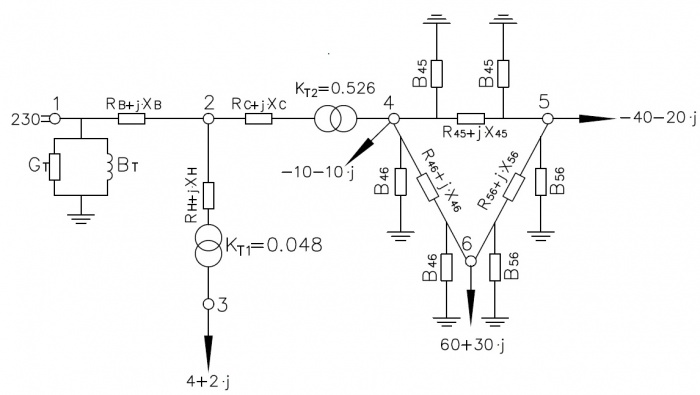
Схема замещения представлена на Рисунке 2.
Справочные данные для АТДЦТН-63000/220/110
- [math]\displaystyle 100/100/50[/math];
- [math]\displaystyle u_{в-с}=11[/math] %;
- [math]\displaystyle u_{в-н}=35[/math] %;
- [math]\displaystyle u_{с-н}=22[/math] %;
- [math]\displaystyle P_{в-с}=215[/math] кВт;
- [math]\displaystyle P_{хх}=45[/math] кВт;
- [math]\displaystyle I_{хх}=0,5[/math] %;
- [math]\displaystyle K_{Т1}=\frac{11}{230} = 0,048[/math]
- [math]\displaystyle К_{T2}=\frac{121}{230} = 0,526[/math].
Расчёт параметров схемы замещения трансформатора
Описание схемы замещения трансформатора представлено здесь.
- Поперечные параметры
- [math]\displaystyle G_{т}=\frac{Pхх}{Uном^{2}}=\frac{0,045}{230^{2}}=8,507\cdot 10^{-7}[/math] См;
- [math]\displaystyle B_{т}=\frac{Iхх\cdot S_{ном}}{100\cdot Uном^{2}}=\frac{0,5\cdot 63}{100\cdot 230^{2}}=5,955\cdot10^{-6}[/math] См;
- Продольные параметры
- [math]\displaystyle U_{кв}=\frac{u_{в-с}+u_{в-н}-u_{с-н}}{2}=12[/math] %;
- [math]\displaystyle U_{кс}=\frac{u_{в-с}+u_{с-н}-u_{в-н}}{2}=0[/math] %;
- [math]\displaystyle U_{кн}=\frac{u_{с-н}+u_{в-н}-u_{в-с}}{2}=23[/math] %;
- [math]\displaystyle X_{в}=\frac{U_{кв}\cdot U_{ном}^{2}}{100\cdot S_{ном}}=\frac{12\cdot 230^{2}}{100\cdot 63}=100,762[/math] Ом;
- [math]\displaystyle X_{с}=\frac{U_{кс}\cdot U_{ном}^{2}}{100\cdot S_{ном}}=\frac{0\cdot 230^{2}}{100\cdot 63}=0[/math] Ом (согласно справочнику Д.Л. Файбисовича);
- [math]\displaystyle X_{н}=\frac{U_{кн}\cdot U_{ном}^{2}}{100\cdot S_{ном}}=\frac{23\cdot 230^{2}}{100\cdot 63}=193,127[/math] Ом;
- [math]\displaystyle R_{в}=R'_{с}=\frac{R'_{н}}{2}[/math];
- [math]\displaystyle R_{в}=\frac{P_{в-с}\cdot U_{ном}^{2}}{2\cdot S_{ном}^{2}}=\frac{0,215\cdot 230^{2}}{2\cdot 63^{2}}=1,433[/math] Ом;
- [math]\displaystyle R_{с}=1,433[/math] Ом;
- [math]\displaystyle R_{н}=2,866[/math] Ом.
Расчёт параметров схемы замещения ЛЭП
Справочные данные для расчёта параметров ЛЭП приведены здесь.
Описание схемы замещения ЛЭП приведено здесь.
- ЛЭП 4-5
- [math]\displaystyle L=60[/math] км — протяженность линии;
- [math]\displaystyle N=3[/math] — количество цепей;
- [math]\displaystyle m=1[/math] — число проводов в фазе;
- [math]\displaystyle D_{ср}=5[/math] м — среднегеометрическое расстояние между проводами цепи;
- [math]\displaystyle R_{0}=0,118[/math] Ом/км;
- [math]\displaystyle X_{0}=0,1445\cdot\log{\frac{D_{ср}}{r_{э}\cdot10^{-3}}} = 0,401[/math] Ом/км;
- [math]\displaystyle B_{0}=\frac{7,58\cdot10^{-6}}{log{\frac{D_{ср}}{r_{э}\cdot10^{-3}}}} = 2,844\cdot10^{-6}[/math] См/км;
- [math]\displaystyle R_{45}=R_{0}\cdot \frac{L}{N} = 0,118\cdot \frac{60}{3} = 2,36[/math] Ом;
- [math]\displaystyle X_{45}=X_{0}\cdot\frac{L}{N} = 8,017[/math] Ом;
- [math]\displaystyle B_{45}=B_{0}\cdot{L}\cdot{N} = 5,119\cdot{10^{-4}}[/math] См.
- ЛЭП 4-6
- [math]\displaystyle L=20[/math] км;
- [math]\displaystyle N=1[/math];
- [math]\displaystyle R_{46}=R_{0}\cdot \frac{L}{N} = 0,118\cdot \frac{20}{1} = 2,36[/math] Ом;
- [math]\displaystyle X_{46}=X_{0}\cdot\frac{L}{N} = 8,017[/math] Ом;
- [math]\displaystyle B_{46}=B_{0}\cdot{L}\cdot{N} = 5,687\cdot{10^{-4}}[/math] См.
- ЛЭП 5-6
- [math]\displaystyle L=40[/math] км;
- [math]\displaystyle N=2[/math];
- [math]\displaystyle R_{56} = R_{0} \cdot \frac{L}{N} = 0,118 \cdot \frac{40}{2} = 2,36[/math] Ом;
- [math]\displaystyle X_{56} = X_{0} \cdot \frac{L}{N} = 8,017[/math] Ом;
- [math]\displaystyle B_{56} = B_{0} \cdot {L}\cdot{N} = 2,275 \cdot {10^{-4}}[/math] См.
Итоговые параметры схемы замещения
- [math]\displaystyle \underline{Z}_{12} = R_{в} + j \cdot X_{в} = 1,433 + j \cdot 100,762[/math] Ом;
- [math]\displaystyle \underline{Y}_{12} = G_{т} - j \cdot B_{т} = 8,507 \cdot 10^{-7} - j \cdot 5,955 \cdot 10^{-6}[/math] См;
- [math]\displaystyle \underline{Z}_{23} = R_{н} + j \cdot X_{н} = 2,866 + j \cdot 193,127[/math] Ом;
- [math]\displaystyle \underline{Z}_{24} = R_{с} + j \cdot X_{с} = 1,433 + j \cdot 0[/math] Ом;
- [math]\displaystyle \underline{Z}_{45} = R_{45} + j \cdot X_{45} = 2,36 + j \cdot 8,017[/math] Ом;
- [math]\displaystyle \underline{Y}_{45} = j \cdot \frac{B_{45}}{2} = j \cdot 2,559 \cdot 10^{-4}[/math] См;
- [math]\displaystyle \underline{Z}_{46} = R_{46} + j \cdot X_{46} = 2,36 + j \cdot 8,017[/math] Ом;
- [math]\displaystyle \underline{Y}_{46} = j \cdot \frac{B_{46}}{2} = j \cdot 2,844\cdot 10^{-4}[/math] См;
- [math]\displaystyle \underline{Z}_{56} = R_{56} + j \cdot X_{56} = 2,36 + j \cdot 8,017[/math] Ом;
- [math]\displaystyle \underline{Y}_{56} = j \cdot \frac{B_{56}}{2} = j \cdot 1,137 \cdot 10^{-4}[/math] См.
Расчёт кольца без учета потерь мощности
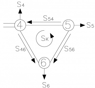
С целью определения точки потокораздела необходимо выполнить расчёт потокораспределения мощностей без учёта продольных потерь мощности в ветвях. Условно-положительные направления потоков мощностей представлены на Рисунке 3.
Для удобства дальнейших расчётов необходимо эквивалентировать мощности шунтов в узлы:
- [math]\displaystyle \underline{Y}_{4} = \underline{Y}_{45} + \underline{Y}_{46} = j \cdot 5,403 \cdot 10^{-4}[/math] См;
- [math]\displaystyle \Delta\dot{S}_{4} = |\dot{U}_{4}|^{2}\cdot\hat{Y}_{4} = -j \cdot 7.911 [/math] МВА;
- [math]\displaystyle \underline{Y}_{5} = \underline{Y}_{45} + \underline{Y}_{56} = j \cdot 3.696 \cdot 10^{-4}[/math] См;
- [math]\displaystyle \Delta\dot{S}_{5} = |\dot{U}_{5}|^{2}\cdot\hat{Y}_{5} = -j \cdot 5.411 [/math] МВА;
- [math]\displaystyle \underline{Y}_{6} = \underline{Y}_{56} + \underline{Y}_{46} = j \cdot 3.981 \cdot 10^{-4}[/math] См;
- [math]\displaystyle \Delta\dot{S}_{6} = |\dot{U}_{6}|^{2}\cdot\hat{Y}_{6} = -j \cdot 5,829 [/math] МВА;
Пересчёт мощностей в узлах:
- [math]\displaystyle\dot{S}_{4} = \dot{S}_{4} + \Delta\dot{S}_{4} = -10 -j \cdot 17,911 [/math] МВА;
- [math]\displaystyle\dot{S}_{5} = \dot{S}_{5} + \Delta\dot{S}_{5} = -40 -j \cdot 25,411 [/math] МВА;
- [math]\displaystyle\dot{S}_{6} = \dot{S}_{6} + \Delta\dot{S}_{6} = 60 +j \cdot 24,171 [/math] МВА;
Примем следующее допущение: пусть напряжения во всей электрической сети постоянно и не зависит от распределения потоков мощностей. С учётом того, что продольные потери мощности отсутствуют, то поток мощности в начале ветви равен потоку мощности в конце ветви.
Пусть мощность ветви 4-5 равной контурной (головной поток), тогда:
- [math]\displaystyle \dot{S}_{54}=\dot{S}_{k}[/math].
В соответствии с первым законом Кирхгофа для узлов (5),(6):
- [math]\displaystyle \dot{S}_{56}= -\dot{S}_{k}-\dot{S}_{5}[/math];
- [math]\displaystyle \dot{S}_{46}=\dot{S}_{6}-\dot{S}_{56}[/math].
Можно выразить и найти контурный поток:
- [math]\displaystyle \dot{S}_{k} = \frac{\dot{S}_{5}\cdot (\hat{Z}_{56}+\hat{Z}_{46})+\dot{S}_{6}\cdot \hat{Z}_{46}}{\hat{Z}_{45}+\hat{Z}_{56}+\hat{Z}_{46}} [/math] МВА.
- [math]\displaystyle \dot{S}_{k} = \frac{(-40-j\cdot 25,411)\cdot (2,36-j\cdot 8,017+2,36-j\cdot 8,017)+(60+j\cdot 24,171)(2,36-j\cdot 8,017)}{2,36-j\cdot 8,017+2,36-j\cdot 8,017+2,36-j\cdot 8,017} = -6,667 - j\cdot 8,884[/math] МВА.
Тогда потоки мощности по всем остальным линиям кольца:
- [math]\displaystyle \dot{S}_{54}=\dot{S}_{k} = -6,667 - j\cdot 8,884[/math] МВА;
- [math]\displaystyle \dot{S}_{56}=\dot{S}_{k}-\dot{S}_{5} = -6,667 - j\cdot 8,884-(-40-j\cdot 25,411) = 33,333 + j\cdot 16,528[/math] МВА;
- [math]\displaystyle \dot{S}_{46}=\dot{S}_{6}-\dot{S}_{56} = 60+j\cdot 24,171-(33,333+j\cdot 16,528) = 26,667+j\cdot 7,644[/math] МВА.
Пусть точка потокораздела - узел(6).
Итерация 1
Начальные приближения
- [math]\displaystyle \dot{U_{1}} = 230 [/math] кВ;
- [math]\displaystyle \dot{U_{2}} = 230 [/math] кВ;
- [math]\displaystyle \dot{U_{3}} = 11 [/math] кВ;
- [math]\displaystyle \dot{U_{3`}}= 230[/math] кВ - напряжение до коэффициента трансформации 1;
- [math]\displaystyle \dot{U_{4}} = 121 [/math] кВ;
- [math]\displaystyle \dot{U_{5}} = 121 [/math] кВ;
- [math]\displaystyle \dot{U_{6}} = 121 [/math] кВ.
Расчёт получившейся радиальной сети
Рисунок 4.
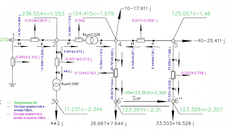
Производим расчёт согласно рисунку 4 (полученные два радиальные сети удобнее считать как одну, сначала прямым ходом по мощностям от узлов (6``) и (6`) к базовому узлу (1) а затем обратным ходом по напряжениям от базового к (6`) и (6``)).
- Прямой ход по мощностям
- [math]\displaystyle \dot{S}_{56``к}=\dot{S}_{56} = 33,333+j\cdot 16,528[/math] МВА;
- [math]\displaystyle \Delta \dot{S}_{46``} = \frac{(P_{56``к}^{2}+Q_{56``к}^{2})\cdot \underline{Z}_{56}}{|\dot U_{6}|^{2}} = \frac{(33,333^{2}+16,528^{2})\cdot (2,36+j\cdot 8,017)}{121^{2}} = 0,223+j\cdot 0,758[/math] МВА;
- [math]\displaystyle \dot{S}_{56``н}=\dot{S}_{56``к}+\Delta \dot{S}_{46``} = 33,333 + j\cdot 16,528+0,223+j\cdot 0,758 = 33,556+ j\cdot 17,286[/math] МВА;
- [math]\displaystyle \dot{S}_{45к}=-\dot{S}_{5}-\dot{S}_{56``н} = -(-40-j\cdot 25,411)-(33,556+j\cdot 17,286) = 6,444+ j\cdot 8,126[/math] МВА;
- [math]\displaystyle \Delta \dot{S}_{45} = \frac{(P_{45к}^{2}+Q_{45к}^{2})\cdot \underline{Z}_{45}}{|\dot U_{5}|^{2}} = \frac{(6,444^{2}+8,126^{2})\cdot (2,36+j\cdot 8,017)}{121^{2}} = 0,017+j\cdot 0,059[/math] МВА;
- [math]\displaystyle \dot{S}_{45н}=\dot{S}_{45к}-\Delta\dot{S}_{45} = (6,444+j\cdot 8,126)-(0,017+j\cdot 0,059) = 6,426+ j\cdot 8,067[/math] МВА;
- [math]\displaystyle \dot{S}_{46`к}=\dot{S}_{46} = 26,667+j\cdot 7,644[/math] МВА;
- [math]\displaystyle \Delta \dot{S}_{46`} = \frac{(P_{46`к}^{2}+Q_{46`к}^{2})\cdot \underline{Z}_{46}}{|\dot U_{6}|^{2}} = \frac{(26,667^{2}+7,644^{2})\cdot (2,36+j\cdot 8,017)}{121^{2}} = 0,124+j\cdot 0,421[/math] МВА;
- [math]\displaystyle \dot{S}_{46`н}=\dot{S}_{46`к}+\Delta\dot{S}_{46`} = (26,667+j\cdot 7,644)+(0,124+j\cdot 0,421) = 26,791+j\cdot 8,065[/math] МВА;
- [math]\displaystyle \dot{S}_{24к}=-\dot{S}_{45н}+\dot{S}_{46`н}+\dot{S}_{4} = -(6,426+j\cdot 8,067)+(26,791+j\cdot 8,065)+(-10-j\cdot 17,911) = 10,365-j\cdot 17,912[/math] МВА;
- [math]\displaystyle \Delta \dot{S}_{24} = \frac{(P_{24к}^{2}+Q_{24к}^{2})\cdot \underline{Z}_{24}}{|\dot U_{4}|^{2}} = \frac{(10,365^{2}+(-17,912)^{2})\cdot (1,433+j\cdot 0)}{121^{2}} = 0,042[/math] МВА;
- [math]\displaystyle \dot{S}_{24н}=\dot{S}_{24к}+\Delta\dot{S}_{24} = (10,365-j\cdot 17,912)+(0,042) = 10,406-j\cdot 17,912[/math] МВА;
- [math]\displaystyle \dot{S}_{23к}=\dot{S}_{3} = 4+j\cdot 2[/math] МВА;
- [math]\displaystyle \Delta \dot{S}_{23} = \frac{(P_{23к}^{2}+Q_{23к}^{2})\cdot \underline{Z}_{23}}{|\dot U_{3`}|^{2}} = \frac{(4^{2}+2^{2})\cdot (2,866+j\cdot 193,127)}{230^{2}} = 1,084\cdot 10^{-3}+j\cdot 0,073[/math] МВА;
- [math]\displaystyle \dot{S}_{23н}=\dot{S}_{23к}+\Delta\dot{S}_{23} = (4+j\cdot 2)+(1,084\cdot 10^{-3}+j\cdot 0,073) = 4,001+j\cdot 2,073[/math] МВА;
- [math]\displaystyle \dot{S}_{12к}=\dot{S}_{24н}+\dot{S}_{23н} = (10,406-j\cdot 17,912)+(4,001+j\cdot 2,073) = 14,408-j\cdot 15,839[/math] МВА;
- [math]\displaystyle \Delta \dot{S}_{12} = \frac{(P_{12к}^{2}+Q_{12к}^{2})\cdot \underline{Z}_{12}}{|\dot U_{2}|^{2}} = \frac{(14,408^{2}-15,839^{2})\cdot (1,433+j\cdot 100,762)}{230^{2}} = 0,012+j\cdot 0,873[/math] МВА;
- [math]\displaystyle \dot{S}_{12н}=\dot{S}_{12к}+\Delta\dot{S}_{12} = (14,408-j\cdot 15,839)+(0,012+j\cdot 0,873) = 14,42-j\cdot 14,966[/math] МВА;
- [math]\displaystyle \Delta\dot{S}_{1} = |\dot{U}_{1}|^{2}\cdot\hat{Y}_{1} = 230^{2}\cdot (8,507-j \cdot 5,955)\cdot10^{-6} = 0,045+j\cdot 0,315[/math] МВА;
- [math]\displaystyle \dot{S}=\dot{S}_{12н}+\Delta\dot{S}_{1} = (14,42-j\cdot 14,966)+(0,045+j\cdot 0,315) = 14,465-j\cdot 14,651[/math] МВА; (Поток мощности, поступающий в сеть).
- Теперь обратный ход по напряжениям.
Напряжение узла (2):
- [math]\displaystyle \Delta \dot{U}_{12} = \frac{P_{12н}\cdot R_{12}+Q_{12н}\cdot X_{12}}{|\dot U_{1}|} = \frac{14,42\cdot 1,433+(-14,966)\cdot 100,762}{230} = -6,467[/math] кВ;
- [math]\displaystyle \delta \dot{U}_{12} = \frac{P_{12н}\cdot X_{12}-Q_{12н}\cdot R_{12}}{|\dot U_{1}|} = \frac{14,42\cdot 100,762-(-14,966)\cdot 1,433}{230} = 6,411[/math] кВ;
- [math]\displaystyle \dot U_{2}=|\dot U_{1}|-\Delta U_{12} - j\cdot\delta U_{12} = 230 - (-6,467)-j\cdot 6,411 = 236,467 - j\cdot 6,411[/math] кВ;
- [math]\displaystyle \dot U_{2}=236,554\angle -1,553^\circ[/math] кВ.
Напряжение узла (3):
- [math]\displaystyle \Delta \dot{U}_{23} = \frac{P_{23н}\cdot R_{23}+Q_{23н}\cdot X_{23}}{|\dot U_{2}|} = \frac{4,001\cdot 2,866+2,073\cdot 193,127}{236,554} = 1,741[/math] кВ;
- [math]\displaystyle \delta \dot{U}_{23} = \frac{P_{23н}\cdot X_{23}-Q_{23н}\cdot R_{23}}{|\dot U_{2}|} = \frac{4,001\cdot 193,127-2,073\cdot 2,866}{236,554} = 3,241[/math] кВ;
- [math]\displaystyle \dot U_{3}=(|\dot U_{2}|-\Delta U_{23} - j\cdot\delta U_{23})\cdot K_{T1} = (236,554 - 1,741-j\cdot 3,241)\cdot 0,048 = 11,23 - j\cdot 0,155 = 11,231\angle -0,791^\circ[/math] кВ;
- [math]\displaystyle \dot U_{3} = 11,231 \angle (-1,553^\circ + (-0,791)^\circ) = 11,231 \angle -2,344^\circ [/math] кВ. - напряжение узла (3), действительный угол вычисляется как сумма углов узла (2) и (3).
Напряжение узла (4):
- [math]\displaystyle \Delta \dot{U}_{24} = \frac{P_{24н}\cdot R_{24}+Q_{24н}\cdot X_{24}}{|\dot U_{2}|} = \frac{10,406\cdot 1,433-17,912\cdot 0}{236,554} = 0,063[/math] кВ;
- [math]\displaystyle \delta \dot{U}_{24} = \frac{P_{24н}\cdot X_{24}-Q_{24н}\cdot R_{24}}{|\dot U_{2}|} = \frac{10,406\cdot 0-(-17,912)\cdot 1,433}{236,554} = 0,109[/math] кВ;
- [math]\displaystyle \dot U_{4}=(|\dot U_{2}|-\Delta U_{24} - j\cdot\delta U_{24})\cdot K_{T2} = (236,554 - 0,063-j\cdot 0,109)\cdot 0,526 = 124,415 - j\cdot 0,057 = 124,415\angle -0,026^\circ[/math] кВ;
- [math]\displaystyle \dot U_{4} = 124,415 \angle (-1,553^\circ + (-0,026)^\circ) = 124,415 \angle -1,579^\circ [/math] кВ. - напряжение узла (4), действительный угол вычисляется как сумма углов узла (2) и (4).
Напряжение узла (6`):
- [math]\displaystyle \Delta \dot{U}_{46`} = \frac{P_{46`н}\cdot R_{46}+Q_{46`н}\cdot X_{46}}{|\dot U_{4}|} = \frac{26,791\cdot 2,36+8,065\cdot 8,017}{124,415} = 1,028[/math] кВ;
- [math]\displaystyle \delta \dot{U}_{46`} = \frac{P_{46`н}\cdot X_{46}-Q_{46`н}\cdot R_{46}}{|\dot U_{4}|} = \frac{26,791\cdot 8,017-(8,065)\cdot 2,36}{124,415} = 1,573[/math] кВ;
- [math]\displaystyle \dot U_{6`}=|\dot U_{4}|-\Delta U_{46`} - j\cdot\delta U_{46`} = 124,415 - 1,028-j\cdot 1,573 = 123,387 - j\cdot 1,573 = 123,397\angle -0,731^\circ[/math] кВ;
- [math]\displaystyle \dot U_{6`} = 123,397 \angle (-1,579^\circ + (-0,731)^\circ) = 123,397 \angle -2,31^\circ [/math] кВ. - напряжение узла (6`), действительный угол вычисляется как сумма углов узла (4) и (6`).
Напряжение узла (5):
- [math]\displaystyle \Delta \dot{U}_{45} = \frac{P_{45н}\cdot R_{45}+Q_{45н}\cdot X_{45}}{|\dot U_{4}|} = \frac{6,426\cdot 2,36+8,067\cdot 8,017}{124,415} = 0,642[/math] кВ;
- [math]\displaystyle \delta \dot{U}_{45} = \frac{P_{45н}\cdot X_{45}-Q_{45н}\cdot R_{45}}{|\dot U_{4}|} = \frac{6,426\cdot 8,017-8,067\cdot 2,36}{124,415} = 0,261[/math] кВ;
- [math]\displaystyle \dot U_{5}=|\dot U_{4}|+\Delta U_{45} + j\cdot\delta U_{45} = 124,415 + 0,642+j\cdot 0,261 = 125,056 + j\cdot 0,261 = 125,057\angle 0,12^\circ[/math] кВ;
- [math]\displaystyle \dot U_{5} = 125,057 \angle (-1,579^\circ + 0,12^\circ) = 125,057 \angle -1,46^\circ [/math] кВ. - напряжение узла (5), действительный угол вычисляется как сумма углов узла (4) и (5).
Напряжение узла (6``):
- [math]\displaystyle \Delta \dot{U}_{56``} = \frac{P_{56``н}\cdot R_{56}+Q_{56``н}\cdot X_{56}}{|\dot U_{5}|} = \frac{33,556\cdot 2,36+17,286\cdot 8,017}{125,057} = 1,741[/math] кВ;
- [math]\displaystyle \delta \dot{U}_{56``} = \frac{P_{56``н}\cdot X_{56}-Q_{56``н}\cdot R_{56}}{|\dot U_{5}|} = \frac{33,556\cdot 8,017-17,286\cdot 2,36}{125,057} = 1,825[/math] кВ;
- [math]\displaystyle \dot U_{6``}=|\dot U_{5}|-\Delta U_{56``} - j\cdot\delta U_{56``} = 125,057-1,741-j\cdot 1,825 = 123,315 - j\cdot 1,825 = 123,329\angle -0,848^\circ[/math] кВ;
- [math]\displaystyle \dot U_{6``} = 123,329 \angle (-1,46^\circ + (-0,848)^\circ) = 123,329 \angle -2,307^\circ [/math] кВ. - напряжение узла (6``), действительный угол вычисляется как сумма углов узла (5) и (6``).
Напряжение узла (6) (как среднее значение напряжений узлов (6`) и (6``):
- [math]\displaystyle \dot U_{6} = \frac{\dot U_{6`}+\dot U_{6``}}{2} = \frac{123,397 \angle -2,31^\circ + 123,329 \angle -2,307^\circ } {2} = 123,363 \angle -2,309^\circ[/math] кВ.
- Расчёт уравнительного перетока
- [math]\displaystyle \dot S_{ур} = \frac{\dot U_{6'}+\dot U_{6''}}{2}\cdot\frac{\hat U_{6'}-\hat U_{6''}}{\hat Z_{45} + \hat Z_{56} + \hat Z_{46}} = \frac{123,397 \angle -2,31^\circ + 123,329 \angle -2,307^\circ}{2}\cdot\frac{123,397 \angle -2,31^\circ - 123,329 \angle -2,307^\circ}{2,36-j\cdot 8,017 + 2,36-j\cdot 8,017 + 2,36 - j\cdot 8,017} = 0,562 - j \cdot 0,551[/math] МВА.
Направление уравнительного потока от узла (6`) к узлу (6``) (из узла с большим потенциалом в узел с меньшим потенциалом).
Уточнение мощностей в узлах (6`) и (6``):
- [math]\displaystyle \dot{S}_{6`}=\dot{S}_{46`к}+\dot S_{ур} = 26,667+j\cdot 7,644+0,562-j\cdot 0,551 = 27,229+j\cdot 7,093[/math] МВА;
- [math]\displaystyle \dot{S}_{6``}=\dot{S}_{56``к}-\dot S_{ур} = 33,333+j\cdot 16,528-(0,562-j\cdot 0,551) = 32,771+j\cdot 17,078[/math] МВА.
В узел с большим потенциалом необходимо добавить уравнительный переток мощности, а из узла с меньшим потенциалом вычесть.
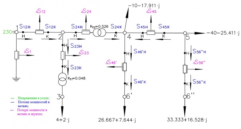
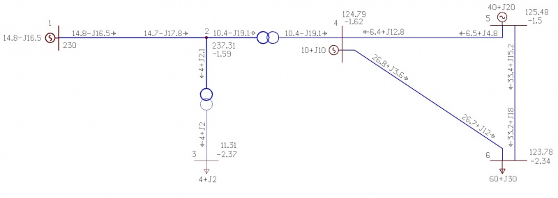
Все данные представлены на рисунке 5. Результаты расчёта с помощью ПК RastrWin представлены на рисунке 6.
Рисунок 5.
Рисунок 6.
Данные для второй итерации
- [math]\displaystyle \dot{U_{1}} = 230\angle 0^\circ [/math] кВ;
- [math]\displaystyle \dot{U_{2}} = 236,554\angle -1,553^\circ [/math] кВ;
- [math]\displaystyle \dot{U_{3}} = 11,231\angle -2,344^\circ [/math] кВ;
- [math]\displaystyle \dot{U_{4}} = 124,415\angle -1,579^\circ [/math] кВ;
- [math]\displaystyle \dot{U_{5}} = 125,057\angle -1,46^\circ [/math] кВ;
- [math]\displaystyle \dot{U_{6}} = 123,363\angle -2,309^\circ [/math] кВ.
Файлы для скачивания
Файл:Расчет установившегося режима кольцевой электрической сети.zip
